Electronic Kit Instructions at AF Rayspeed
Electronic Kit Instructions
12 Volt A.C. A.F. Electronic System
This system will fit all Lambretta G.P. models and machines where the original crankcase shaft has been substituted for the G.P.
Kit Consists of: Flywheel, Stator, Regulator, C.D.I. Unit, Junction Box and Cover, two pieces of wire, two lucar terminals.
Fitting Instructions:
- Remove the original flywheel and stator, rectifier, zenor diode (if fitted) and H.T. coil. Refer to the Lambretta manual if necessary for this procedure.
- Secure the stator in to the magflange as normal, making sure that the studs that secure the magflange to the engine, the bolts that secure the stator to the magflange and the clip that secures the stator wires do not sit to proud, otherwise they will catch on the back of the flywheel. When fitting the stator also make sure that you do not trap the stator wires, crushing them against the magflange and possibly causing a short circuit. Fit the stator so that the securing 10mm bolts are in the centre of their respective slots.
- Presuming that your crankshaft taper is in good condition, fit a new woodruff key, and then slot the flywheel on. At this stage do not tighten.
Setting the Ignition timing:
- You must turn the engine over by rotating the flywheel clockwise and find T.D.C.
- On the outer edge of the flywheel at approximately two o’clock, you will find an arrow; tap a notch using a small chisel (or any other suitable sharp implement) on the edge of the magflange right opposite the arrow when the engine is at T.D.C.
- Now, if you have a timing disc then secure it to the flywheel and turn the flywheel 21º anti clockwise, and again make a notch in the magflange right opposite the arrow. If you do not have a timing disc then take a rule and measure 1 and 1/8 inch anticlockwise from the T.D.C. notch and mark the magflange, again on the outer lip.
- Now, if you look at the window on the flywheel (at five o’clock), you will see two small lines inscribed. These two lines have to match up exactly with the line on the black pick up box on the stator, when the arrow on the flywheel is pointing at the 21º or 1 and 1/8 notch. If the two lines on the flywheel are further round then slacken the three 10mm stator bolts and turn the stator clockwise until the timing is correct. Secure the stator bolts. If the two lines on the flywheel are in front of the pick up box mark, then slacken off the three 10mm stator bolts and turn the stator anticlockwise until the timing is correct. Secure the stator bolts. Now the timing is set and will never alter.
- Secure the flywheel to 50 ft lbs. If the flywheel does not turn freely then check for the cause (stator bolts, damaged magflange, twisted crankshaft).
- Fit the original flywheel dust cover and circlips.
- The electronic flywheel has larger cooling fins than the original Italian flywheel; therefore your original cowling may not fit. You will have to purchase the later type as fitted to the majority of Indian G.P.’s. I do not recommend running the engine without the mag cowling fitted.
Continuation of Assembly: (from No. 3 of fitting instructions)
You will need an electric drill and 10mm mounting bolts.
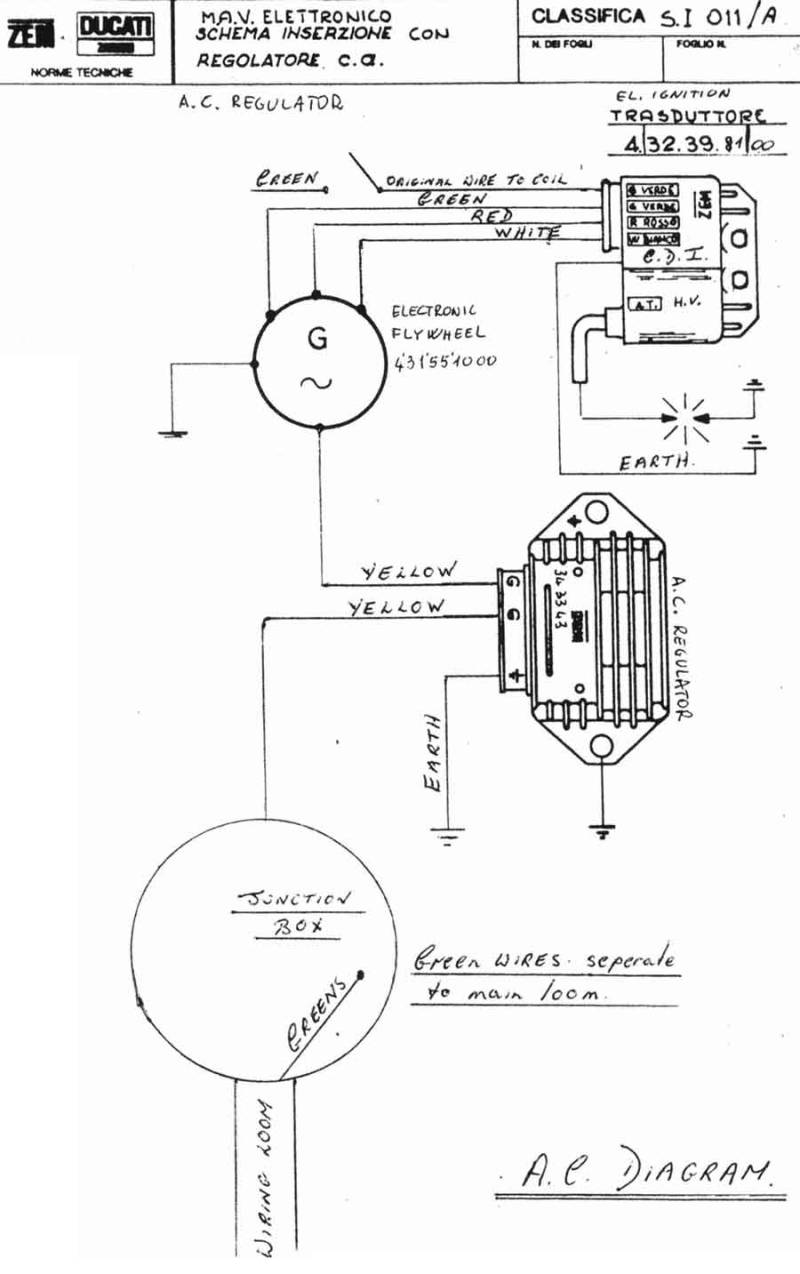
- Fit the junction box to the nearside footboard frame leg. Fit H.T. lead to the C.D.I.unit.
- Secure the regulator C.D.I. unit somewhere close to the junction box. Make sure that the regulator is well earthed and solidly mounted. It must not be near any heat source. Take the earth wire of the C.D.I. unit and secure under one of it’s mounting bolts or another suitable earth position.
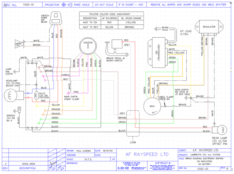
- Wire up the regulator and C.D.I. as per the diagram. Take the original green wire that went to the H.T. coil, fit with the lucar terminal supplied and fit to the C.D.I. unit.
- Take the wires of the main wiring loom and push in to the junction box (anywhere) except for the two green wires (joined), which must go in to the marked green hole, or the two greens can be taped, but in no way come in to contact with the lighting circuitry.
- The yellow wire supplied, push in to the junction box and then to the regulator. (G) as shown.
- Fit the other wire supplied as an earth wire for the regulator.
- If the original machine was fitted with a battery then tape up the battery feed wires. If your machine was previously fitted with 6 Volt bulbs then replace them with 12 Volt ones.
- Check for a spark, start the engine and check the lights.